valve-flap2d
English | Japanese
« Home · « Particles and fluid-structure interaction
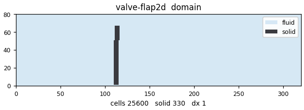
Hinged flap / check-valve FSI: a rigid thin flap hinged at one edge on the channel floor, immersed in a 2D duct flow, that rotates about its hinge under the hydrodynamic load and a restoring torsional spring. The canonical reed / check-valve building block, validated against a QUASI-STATIC torque balance.
Geometry
Animation
Fields
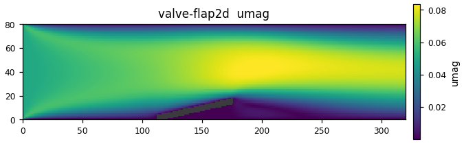
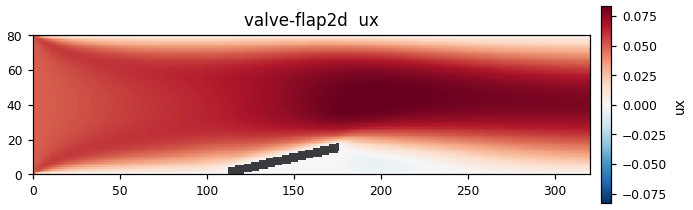
The fields this computation wrote at its last output step, plotted as they are. 3D cases show the mid-plane.
Results
Solves for a rigid flap hinged to the floor (L = 65.6, thickness 5 cells, hinge (112, 1)) until it settles at the static equilibrium angle where the fluid torque of the duct flow balances a torsion spring. Grid 320×80, TRT (τ = 0.6, ν = 3.3333e-2), uniform inflow U = 0.05 (forward direction, Re_L = 98.4, dynamic pressure q = ½ρU² = 1.25e-3), spring k = 6.0, θ0 = 0, inertia I = 5e6, critical damping c = 10954.45 (1.00×crit), force low-pass relax = 0.05. 120 000 steps, wall-clock time 38.6 s on 72 Grace CPU cores.
The transient is a clean critically damped rise: θ = 1.15° (initial) → 49.97° (step 5000) → 75.13° (step 10000), settling at step 11000 (drift 0.00e+00/step), after which it does not move to 4 decimal places over 119 000 steps. The numbers at equilibrium:
| Quantity | Value | Check |
|---|---|---|
| θ_eq | 77.3493° = 1.3500 rad | — |
| M_spring | 8.100 | k·θ = 6.0×1.3500 = 8.100 ✓ |
| M_mem | 15.71721 | MEM torque |
| M_press | 15.60606 | independent surface-pressure integral. Difference (15.717−15.606)/15.717 = 0.71% |
| Q_through | 3.997621 | 99.9% of the inflow flux U·H = 0.05×80 = 4.0 |
| C_M | 121.8353 | fitted coefficient of the flat-plate model |
The core of the verification is 2 points. (1) 2 independent load integrals on the same boundary links (momentum exchange and pressure integral) agree to 0.7%. (2) The equilibrium really is a torque balance — M_spring = kθ_eq holds exactly as an analytic identity, and the difference from the fluid-side M_mem corresponds to the part not stored in the spring (taken up by the hinge/seat constraint). Putting C_M = 121.8353 into the quasi-static flat-plate model \(M=\tfrac12 C_M q L^2\cos^2\theta\) gives ½×121.84×1.25e-3×65.6²×cos²(77.35°) ≈ 15.7, reproducing M_mem.
This run is forward-direction only (flow_dir = 1, tag=case); valve closure under reverse flow (check-valve action) is not included in this gallery run — see Things to try.
Governing equations
The flap is a rigid body with 1 rotational degree of freedom about a fixed hinge:
\[
I_{\mathrm{hinge}}\,\ddot\theta = M_{\mathrm{fluid}}(\theta)
- k(\theta-\theta_0) - c\,\dot\theta
\]
The fluid is D2Q9 TRT (Λ = 3/16). The flap surface is a moving-wall bounce-back carrying the local rotational wall velocity \(\boldsymbol{u}_w=\boldsymbol{\omega}\times(\boldsymbol{x}_b-\boldsymbol{x}_{\mathrm{hinge}})\) (there is no translation). The hinge torque is the momentum exchange on the boundary links:
\[
M_{\mathrm{mem}}=\sum_{\mathrm{links}}(\boldsymbol{x}_b-\boldsymbol{x}_{\mathrm{hinge}})
\times\left[\boldsymbol{c}_j\left(f^{*}_j+f_{\bar j}\right)\right]
\]
and it is checked against the surface-pressure integral M_press on the same boundary. There is no closed-form FSI equilibrium solution, so the verification is (a) agreement of the 2 integrals, and (b) θ_eq(q) following the 1-parameter flat-plate model
\[
M_{\mathrm{model}}(\theta,q)=\tfrac12\,C_M\,q\,L^{2}\cos^{2}\theta
\]
(cos² is frontal projection × moment arm). The force low-pass with relax < 1 affects only the damping of the transient and does not change the static equilibrium (θ̇ → 0). Under reverse flow the rigid seat clamps θ ≥ θ0, giving check-valve action.
Code walkthrough
Source (507 lines; the moving-boundary machinery is reused from dkt2d.cpp).
%%{init: {'themeVariables': {'fontSize': '11px'}}}%%
flowchart LR
    IN["x=0 inflow<br/>Guo non-equilibrium extrapolation<br/>uniform U=0.05"] --> CH
    subgraph CH["Duct 320×80, TRT<br/>halfway BB on top and bottom walls"]
      F["Flap (staircase rectangle)<br/>moving-wall BB u=ω×r<br/>MEM torque + pressure integral"]
    end
    CH --> OUT["x=Nx-1 outflow<br/>fixed pressure"]
F --- H(("Hinge (112,1)<br/>spring k + damping c + seat"))- Mask — re-rasterize the rotated rectangle as a staircase every step according to θ.
- collide/stream — TRT. Moving-wall BB on the flap surface; vacated cells are refilled with equilibrium.
- Loads — the MEM torque and the pressure-integral torque are computed in parallel on the same set of links.
- Rigid 1 DOF update — semi-implicit Euler, with the seat (θ ≥ θ0) and an opening stop (θ ≤ θ_max).
- Settling test — once the drift of θ falls below settle_tol, settled is recorded, and from then on it is
a confirmation interval for the equilibrium value. Output to the SUMMARY line and
valve_case.csv(242 lines).
Build & run
valve_flap2d [config.txt] (KEY=VALUE; or all defaults)
Cost of the computation that made the figures on this page (Miyabi-G Grace CPU (72 cores, -stdpar=multicore)): 38.5 s wall.
Things to try
- Run reverse flow with flow_dir = -1. Measure Q_through at the same |U| and compare with the forward 3.998 to put a number on the valve's asymmetry (check action).
- Sweep U and plot θ_eq(q). How well does the monotonic increase of θ_eq with q = ½ρU² follow the flat-plate model with constant C_M? Look honestly at the residuals.
- Set k to 3 and 12. θ_eq moves according to the balance equation. Confirm that the identity M_spring = kθ_eq holds exactly for any k.
- Set cdamp_frac to 0.2 (underdamped). Settling becomes oscillatory; how much is settled_at delayed? The critical damping of 1.00 is what buys the settling at 11 000 steps in this gallery run.
Validation
| Tier | T2 — single-point comparison |
| QoI | flap_angle |
| Reference | quasi-static torque balance of a hinged flap |
| Gate | 🧩 module gate (rigid_body) |
Source & run details
| Item | Value |
|---|---|
| Target | orheo-valve-flap2d |
| Source | native/benchmarks/valve_flap2d.cpp |
| Lattice | D2Q9 |
| GPU twin | no |
| Gallery run | 2026-07-27 @ 7628c0cf |
| Args | `` |
| Wall time | 38.55 s |
| CPU time | 1468.80 s |
| Device | Miyabi-G Grace CPU (72 cores, -stdpar=multicore) |
Computation log
The actual output of this computation (head and tail).
Hinged flap / check-valve FSI (D2Q9 TRT, moving BB + MEM torque)
  grid 320x80  tau=0.6000 nu=3.3333e-02  U=+0.0500 (dir +1)  Re_L=98.4
  hinge @ (112.0,1.0)  flap L=65.6 thick=5.0 cells
  spring k=6.000 theta0=0.000  I=5000000.0 c=10954.45 (1.00*crit)  relax=0.050
  q_dyn=1.2500e-03  k*rad estimate  maxsteps=120000 tag=case
step       0  theta=  1.15 deg  om=-2.40e-08  M_mem=-9.326e-15 M_press=-0.000e+00 M_spr=+1.200e-01  Q=+1.110e-15
step    5000  theta= 49.97 deg  om=+1.27e-04  M_mem=+6.204e+00 M_press=+6.098e+00 M_spr=+5.233e+00  Q=+2.487e+00
step   10000  theta= 75.13 deg  om=+7.83e-05  M_mem=+9.510e+00 M_press=+9.447e+00 M_spr=+7.868e+00  Q=+3.952e+00
  -> settled at step 11000 (drift=0.00e+00/step)
step   15000  theta= 77.35 deg  om=+0.00e+00  M_mem=+1.586e+01 M_press=+1.573e+01 M_spr=+8.100e+00  Q=+4.015e+00
step   20000  theta= 77.35 deg  om=+0.00e+00  M_mem=+1.591e+01 M_press=+1.580e+01 M_spr=+8.100e+00  Q=+4.017e+00
step   25000  theta= 77.35 deg  om=+0.00e+00  M_mem=+1.574e+01 M_press=+1.563e+01 M_spr=+8.100e+00  Q=+4.015e+00
step   30000  theta= 77.35 deg  om=+0.00e+00  M_mem=+1.570e+01 M_press=+1.559e+01 M_spr=+8.100e+00  Q=+4.003e+00
step   35000  theta= 77.35 deg  om=+0.00e+00  M_mem=+1.568e+01 M_press=+1.557e+01 M_spr=+8.100e+00  Q=+3.997e+00
...

step   95000  theta= 77.35 deg  om=+0.00e+00  M_mem=+1.572e+01 M_press=+1.561e+01 M_spr=+8.100e+00  Q=+3.998e+00
step  100000  theta= 77.35 deg  om=+0.00e+00  M_mem=+1.572e+01 M_press=+1.561e+01 M_spr=+8.100e+00  Q=+3.998e+00
step  105000  theta= 77.35 deg  om=+0.00e+00  M_mem=+1.572e+01 M_press=+1.561e+01 M_spr=+8.100e+00  Q=+3.998e+00
step  110000  theta= 77.35 deg  om=+0.00e+00  M_mem=+1.572e+01 M_press=+1.561e+01 M_spr=+8.100e+00  Q=+3.998e+00
step  115000  theta= 77.35 deg  om=+0.00e+00  M_mem=+1.572e+01 M_press=+1.561e+01 M_spr=+8.100e+00  Q=+3.998e+00
step  120000  theta= 77.35 deg  om=+0.00e+00  M_mem=+1.572e+01 M_press=+1.561e+01 M_spr=+8.100e+00  Q=+3.998e+00

=== SUMMARY tag=case ===
SUMMARY tag=case flow_dir=1 U=0.05000 q_dyn=1.250000e-03 theta_eq_deg=77.3493 M_mem=1.571721e+01 M_press=1.560606e+01 M_spring=8.100000e+00 C_M=121.8353 Q_through=3.997621e+00 settled_at=11000
References
- A. J. C. Ladd, J. Fluid Mech. 271 (1994); C. K. Aidun, Y. Lu & E.-J. Ding, J. Fluid Mech. 373 (1998).
- Z. Guo, C. Zheng & B. Shi, "Non-equilibrium extrapolation method for velocity and pressure boundary conditions in the lattice Boltzmann method", Chin. Phys. 11 (2002) 366.