cylinder2d-d3q19
English | Japanese
« Home · « Laminar flow and analytic verification
D3Q19 (pseudo-2D) laminar flow around a circular cylinder in a plane channel -- the DFG benchmark 2D-2 of Schaefer & Turek (1996), the classic unsteady vortex-shedding external-aero verification case at Re = 100.
Geometry
Animation
Fields
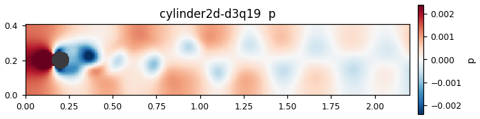
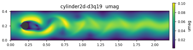
The fields this computation wrote at its last output step, plotted as they are. 3D cases show the mid-plane.
Plots
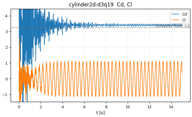
Time series and distributions of the QoI written by this computation. Where a reference value exists it is overlaid as a horizontal line.
Results
Every figure on this page comes from 1 run with nd=20 (20 cells per cylinder diameter, grid 440×82 = 0.04 M cells, dx = 5 mm), 60 000 steps, Ubar = 0.05 lattice units (peak Mach 0.130, τ = 0.53). 8.95 seconds on 72 Grace CPU cores.
The Cd, Cl plot shows the essence of this case: you can see directly how the wake behind the
asymmetrically placed cylinder develops into self-sustained oscillation. Right after start-up Cd jumps to 134
(a pressure wave from imposing the parabolic inflow on a fluid at rest at one instant; it belongs to the initial
condition, not to the physics. The plot clips the vertical axis to the 2–98 percentile, so this spike runs off
the top). By t ≈ 0.5 s Cd has dropped to 4.03; from there the Cl amplitude grows slowly until t ≈ 6 s, after which
the flow settles on a constant-amplitude limit cycle. The animation shows this established Kármán vortex street
travelling downstream; in the second half the period of alternating vortex shedding from the upper and lower sides
can be read clearly.
The computed values and the DFG 2D-2 reference bands are as follows (evaluated over the developed interval of the last 30 000 steps).
| Quantity | This run | Reference band | Difference |
|---|---|---|---|
| Cd_max | 3.5223 | 3.22–3.24 | +8.7% |
| Cl_max | 1.1077 | 0.99–1.01 | +10.7% |
| St | 0.2982 | 0.295–0.305 | within band |
The Strouhal number falls inside the reference band, while the force coefficients are 9–11% high. This is not a contradiction but a known consequence of representing the cylinder with staircase bounce-back. The shedding period is set by the large-scale structure of the wake, so it agrees well even with a coarse wall; the forces, on the other hand, integrate over the immediate vicinity of the wall, so the errors in effective diameter and effective roughness carry straight into them. The source header also states explicitly that a bias of a few % is expected at nd = 20–30. The proper remedy is to raise nd or to switch to Bouzidi interpolated bounce-back (Things to try).
Governing equations
We solve the incompressible Navier–Stokes equations around a cylinder placed in a plane channel.
\[
\nabla\cdot\boldsymbol{u}=0,\qquad
\frac{\partial\boldsymbol{u}}{\partial t}+(\boldsymbol{u}\cdot\nabla)\boldsymbol{u}
=-\frac{1}{\rho}\nabla p+\nu\,\nabla^{2}\boldsymbol{u}
\]
The discretisation is the D3Q19 lattice Boltzmann method. The z direction, however, is 1 cell with a periodic boundary, so the flow is strictly 2-dimensional (D3Q19 is used rather than D2Q9 because we want to verify with the same kernel as the 3D code). The collision is regularised BGK:
\[
f_i(\boldsymbol{x}+\boldsymbol{c}_i,\;t+1)=f_i(\boldsymbol{x},t)
-\omega\left[f_i(\boldsymbol{x},t)-f_i^{\mathrm{eq}}(\rho,\boldsymbol{u})\right],
\qquad \omega=\frac{1}{\tau},\quad \nu=c_s^{2}\left(\tau-\tfrac12\right)
\]
\[
f_i^{\mathrm{eq}}=w_i\,\rho\left(1+\frac{\boldsymbol{c}_i\cdot\boldsymbol{u}}{c_s^{2}}
+\frac{(\boldsymbol{c}_i\cdot\boldsymbol{u})^{2}}{2c_s^{4}}
-\frac{\boldsymbol{u}\cdot\boldsymbol{u}}{2c_s^{2}}\right)
\]
The force on the cylinder is obtained as the sum of momentum exchange over the bounced-back links. For each link \(i\) crossing the wall, we count the momentum carried away by the post-collision distribution \(f_i^{*}\):
\[
\boldsymbol{F}=\sum_{\text{bounced }i} 2\,\boldsymbol{c}_i\,f_i^{*},
\qquad
C_D=\frac{2F_x}{\rho\,\bar U^{2}D},\qquad
C_L=\frac{2F_y}{\rho\,\bar U^{2}D}
\]
Pitfall in pseudo-2D: with Nz = 1 and z periodic, links with \(c_{i,z}\neq 0\) also stream within the plane (the z shift wraps back onto itself). They therefore also bounce off the cylinder and carry x/y momentum. Summing only the links with \(c_{i,z}=0\) drops about 1/3 of the force. This implementation sums all 18 links that cross the in-plane boundary.
Dimensionless numbers (actual values in this run)
- Reynolds number \(\mathrm{Re}=\bar U D/\nu = 100\) (\(\bar U = 0.05\) in lattice units, \(D = 20\) cells, \(\nu = 0.01\))
- Relaxation time \(\tau = 0.53\), peak Mach number 0.130
- Strouhal number \(\mathrm{St}=fD/\bar U\), read from the upward zero crossings of \(C_L(t)\)
Code walkthrough
Source (350 lines, single file).
%%{init: {'themeVariables': {'fontSize': '11px'}}}%%
flowchart LR
    IN["x=0 inflow<br/>Guo non-equilibrium extrapolation<br/>parabolic U(y)"] --> D
    subgraph D["Channel interior<br/>regularised BGK<br/>cylinder = staircase mask"]
    end
    D --> OUT["x=Nx-1 outflow<br/>fixed pressure, zero velocity gradient"]
    D --- W["Top/bottom walls y=0, Ny-1<br/>halfway bounce-back"]
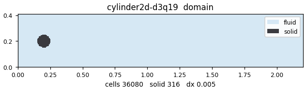
D --- C["Cylinder surface<br/>bounce-back<br/>+ force measured by momentum exchange"]- Geometry and mask — The Schäfer–Turek dimensions (H = 0.41 m, L = 2.2 m, D = 0.1 m, centre (0.2, 0.2)) are mapped onto the grid with dx = D/nd. The cylinder is a staircase mask in which cells satisfying \((x-x_c)^2+(y-y_c)^2 \le R^2\) are made solid. In this run there are 316 solid cells and 35 764 fluid cells.
- Extracting boundary links — Pairs of a fluid cell \(c\) and a direction \(j\) for which \(c+e_j\) falls inside the solid are listed in advance (356 links). Evaluating the force only loops over this list, so the whole grid is not scanned every step.
- collide — Fluid cells only, regularised BGK. The non-equilibrium part is reconstructed from the 2nd-order moments before relaxation, so it is hard to break even as τ → 0.5.
- stream — Pull scheme. If the destination is outside the domain or solid, the opposite distribution is taken in place (halfway bounce-back).
- edges — The inflow and outflow faces are overwritten with Guo's non-equilibrium extrapolation. The inflow has a parabolic velocity; the outflow has a fixed pressure.
- Forces and QoI — Every 20 steps, \(F_x, F_y\) are taken from the boundary-link sum and \(C_D, C_L\) are appended to a CSV. At the end, St is obtained from the upward zero crossings of \(C_L(t)\) over the second-half interval.
- Gallery dump — Only when
ORHEO_WIKI_DUMPis set, ux, uy, p are written out withwiki_dump_grid2d. By default it does nothing, so the behaviour of ctest and production runs does not change by even 1 bit.
Build & run
cmake -S native -B native/build && cmake --build native/build -j
./native/build/orheo-cylinder2d-d3q19
cylinder2d_d3q19 [nd] [steps] [csv_out] [field_out] [umean]
Cost of the computation that made the figures on this page (Miyabi-G Grace CPU (72 cores, -stdpar=multicore)): 28.8 s wall.
Things to try
- Raise
ndfrom 20 → 30 → 40 (argument 1). The effective-diameter error of the staircase mask shrinks, and Cd_max should come down from 3.52 towards the reference band 3.22–3.24. St is already inside the band, so it should barely move — this is a direct check that "the period agrees even with a coarse wall, but the force does not". Raising nd at fixed τ increases the number of steps needed as \(nd^2\). - Lower
umeanfrom 0.05 → 0.025 (argument 5). Mach goes from 0.130 → 0.065 and the compressibility error becomes 1/4, but reaching the same physical time takes twice as many steps. Confirming that its effect on Cd is smaller than the staircase error tells you which one is the main source of error. - Reduce
stepsto 20000 and look at the plots. You can see how much lower Cl_max comes out when evaluated over an interval that has not yet fully settled on the limit cycle. This is why the developed interval is defined as "evaluate over the second half" rather than judged by eye. - Place the cylinder at the vertical centre (y = 0.205). Removing the 5 mm offset written in the header keeps the symmetric solution alive for a long time, and the onset of vortex shedding becomes extremely slow. You get a feel for why the benchmark definition is deliberately asymmetric.
Validation
| Tier | T2 — single-point comparison |
| QoI | drag, lift, pressureDrop |
| Reference | Schaefer & Turek (1996) DFG benchmark 2D-1 (Re=20, Cd~5.58) / 2D-2 (Re=100) |
| Gate | — no gate |
| Measured | 3.4739 (rel. err +7.55%) — cross-code run (cylinder_st_cd) |
Source & run details
| Item | Value |
|---|---|
| Target | orheo-cylinder2d-d3q19 |
| Source | native/benchmarks/cylinder2d_d3q19.cpp |
| Lattice | D3Q19 |
| GPU twin | no |
| Modules | lbm_d3q19.hpp |
| Gallery run | 2026-07-27 @ 7628c0cf |
| Args | 20 60000 cylinder2d.csv "" 0.05 |
| Wall time | 28.84 s |
| CPU time | 935.75 s |
| Device | Miyabi-G Grace CPU (72 cores, -stdpar=multicore) |
Computation log
The actual output of this computation (head and tail).
=== cylinder2d D3Q19 -- Schaefer-Turek 2D-2 (Re=100) ===
nd=20  grid 440x82 (0.04 Mcell)  dx=0.00500 m
Ubar=0.0500 (peak Mach=0.130)  nu=0.01000  tau=0.53000
cylinder: centre cell (39.5,39.5)  R=10.0 cells  channel mid=40.5
solid cells=316  fluid cells=35764
cylinder boundary links=356 (perimeter ~63)
step       0/60000  t=0.000s  Cd=134.4016  Cl=+0.4578
step    2000/60000  t=0.500s  Cd=4.0271  Cl=+0.7426
step    4000/60000  t=1.000s  Cd=4.5704  Cl=-0.1638
step    6000/60000  t=1.500s  Cd=3.6243  Cl=+0.5232
step    8000/60000  t=2.000s  Cd=2.4182  Cl=-0.4942
step   10000/60000  t=2.500s  Cd=3.5577  Cl=+0.8445
step   12000/60000  t=3.000s  Cd=3.4149  Cl=-0.9241
step   14000/60000  t=3.500s  Cd=3.7684  Cl=+0.9047
...

step   58000/60000  t=14.500s  Cd=3.4038  Cl=-0.3748
step   60000/60000  t=15.000s  Cd=3.4121  Cl=+0.3945

=== RESULTS (developed limit cycle, 2nd half) ===
Cd_max = 3.5223   (ref 3.22-3.24)
Cl_max = 1.1077   (ref 0.99-1.01)
Cl_amp = 1.1275   Cl_min=-1.1473
St     = 0.2982   (ref 0.295-0.305)  [22 crossings, T=1341 steps]
staircase nd=20 -- expect a few-% bias vs Bouzidi BB
References
- M. Schäfer & S. Turek, "Benchmark computations of laminar flow around a cylinder", Flow Simulation with High-Performance Computers II, Notes on Numerical Fluid Mechanics 52 (Vieweg, 1996), 547–566.
- Z. Guo, C. Zheng & B. Shi, "Non-equilibrium extrapolation method for velocity and pressure boundary conditions in the lattice Boltzmann method", Chin. Phys. 11 (2002) 366.